5 Lenses
Hecht1 gives the following definition of a lens:
1 “Optics”, fourth edition, by Eugene Hecht
A lens is a refracting device (i.e. a discontinuity in the prevailing medium) that reconfigures a transmitted energy distribution.
Wikipedia states that:
A lens is a transmissive optical device that focuses or disperses a light beam by means of refraction.
As with defining a wave, it is difficult to create an entirely satisfying definition of a lens. It may be more productive to state what we want a lens to achieve for us. In our example, we wish to focus the light from a distant galaxy. In other words, we wish our lens to be able to focus parallel waves to a single focal point2.
2 Such a lens may also be used to take light from a point source, i.e. spherical waves, and convert it to plane waves, i.e. a beam of parallel light rays.
5.1 A simple lens
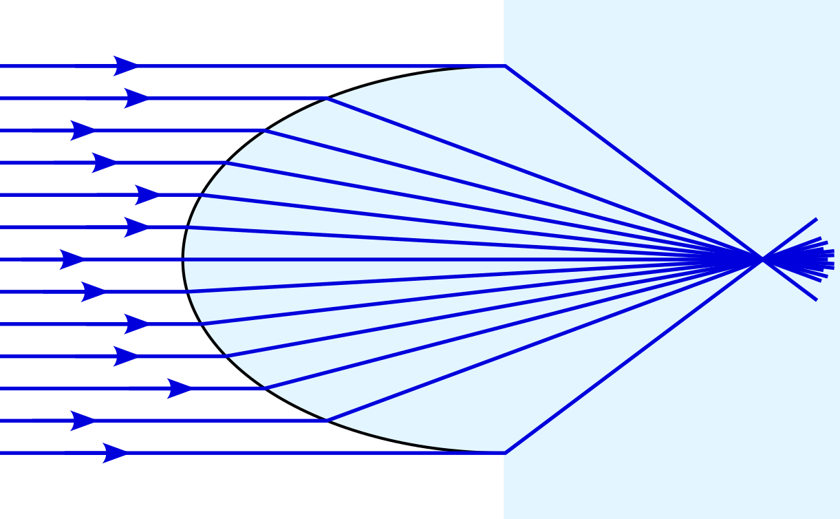
We can attempt to complete our task of focusing parallel waves using a single surface, as shown in figure 5.3.
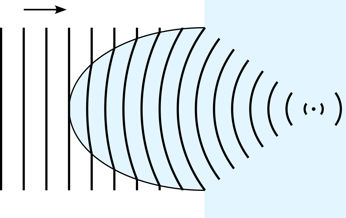
Notice that the top of the wavefront arrives at the focal point at the same time as the bottom and middle3. We may also view this using the notion of rays of light4, perpendicular to the wave fronts, as in figure 5.4.
3 From the initial wave to the focal point there are 17 wavelengths, regardless of which part of the wavefront we consider. The time taken to arrive is therefore \(17/(2\pi\omega)\) for any part of the wave.
4 Geometrical optics is a model of the behaviour of light using rays, ignoring effects such as diffraction and interference.
Consider a single ray.
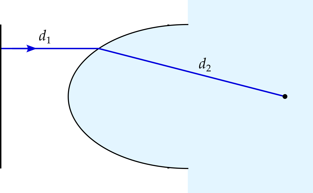
We can calculate how long it takes the light to travel this path — it is simply \[ \frac{d_1}{v_1} + \frac{d_2}{v_2} = \frac{1}{c}\left(n_1d_1 + n_2d_2\right). \] Since this must be the same for each ray, we find that the surface must consist of points satisfying \[ n_1d_1 + n_2d_2 = \text{const}. \] An ellipse5 of appropriate eccentricity, with one of its foci at the position where the light is focused, can be shown6 to satisfy this equation.7
5 Or, in three dimensions, an ellipsoid.
6 See appendix.
7 If the surface is required to be a single, smooth curve, then an ellipsoid (or part of one) is the only shape that will focus the light in this way. However, if the \(x\) coordinate of the surface is permitted to vary discontinuously with \(y\), alternatives can be found. Look up Fresnel lenses if you are interested.
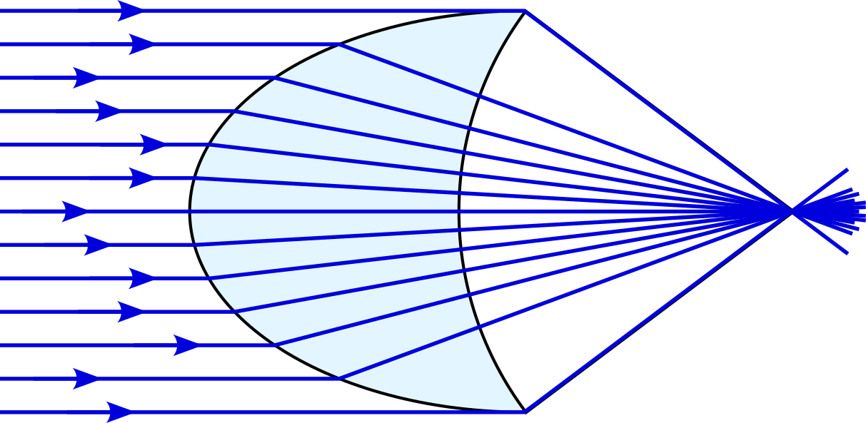
Of course, the lenses with which you are familiar have two surfaces and focus the light at a point outside the glass lens. By cutting away a sphere, centred at the focal point, we create such a lens.
5.2 Aberration
Spherical lenses have a practical advantage — they are easier and cheaper to make. Imagine an object with a convex spherical surface in contact with a concave spherical polishing surface of the same radius. All points of the two surfaces are in contact with the surface, and remain so as the object (or polishing surface) is rotated around the sphere’s centre. In other words, a polishing motion will polish the surface uniformly. Now imagine a bump on the surface8. The same motion will now work to remove this bump.
8 One might equally consider a bump on the polishing surface, which will also be worn away.
9 Or hyperbolic, if we have parallel rays travelling from glass into air.
10 The optical axis.
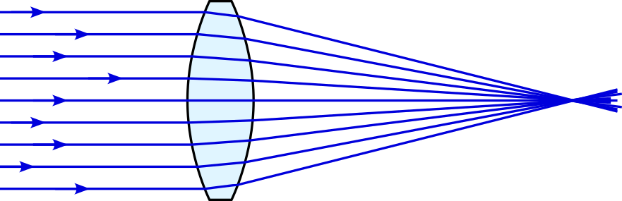
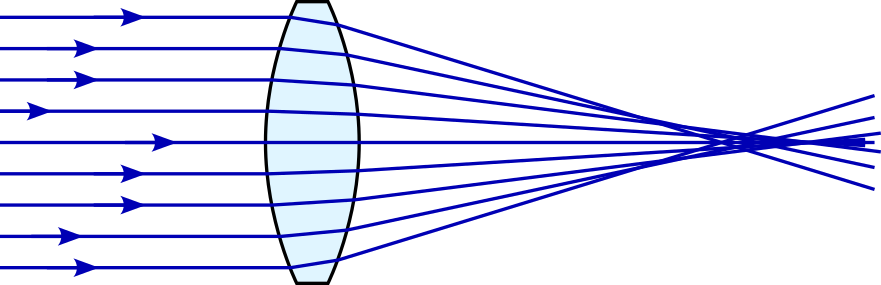
Unfortunately, we have seen that surfaces that perfectly focus light are ellipsoidal9, not spherical. The result is that spherical lenses suffer from spherical aberration, for the simple reason that they are not quite the right shape. Given plane waves entering the lens, rays further from the axis of symmetry10 are deflected more than is necessary, crossing the axis closer to the lens.
Spherical aberration can be minimised by using multiple lenses in combination.
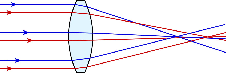
A second form of aberration occurs since even a lens that perfectly focuses one colour of light may not focus a different colour to the same point. In glass, blue light travels more slowly than red light, i.e. glass is a dispersive medium. Hence the refractive index depends on the light colour, with blue light being refracted more than red.